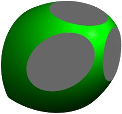
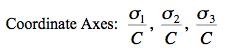
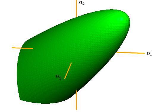
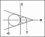
Failure Surface Graphics The graphic shown above is part of the failure surface in principal stress space for a typical brittle isotropic material. The complete failure surface is composed of two parts, the paraboloid shown (as determined by polynomial invariants) and a competing fracture mode of failure that produces planar “fracture cutoffs” from the paraboloid. Mainly the geometric aspects of the failure surfaces will be shown and described here. The physical and mathematical bases of these are the subjects of nearly the entire website and will not be greatly involved here. The complete failure criteria are given by Eqs. (8)-(10) in Section II for isotropic materials. These failure criteria are calibrated by two failure properties, the uniaxial tensile and compressive strengths T and C. The paraboloidal part of the overall failure criterion, from the method of polynomial invariants, has a symmetry axis which makes equal angles with the three principal stress axes, σ1, σ2, and σ3. The fracture criterion planes are normal to the three principal stress axes. In the following graphics, stress is nondimensionalized by the uniaxial compressive strength, C. The examples differ only through the variation of the tensile to compressive strength ratio, T/C. The different T/C values correspond to seven examples from widely different classes of materials, namely ductile metals, ductile polymers, brittle polymers, cast irons, ceramics, glasses, and geological materials. All of these cases are at the same scale, thus allowing direct comparisons between them. In this sequence of computer graphics the scale and the view angle are selected to best observe the brittle end of the sequence rather than the ductile end since the latter is quite well understood. The ductile cases will be further illustrated later. A grouping of small sized images are shown first, followed by large, individual images.
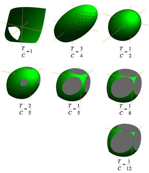
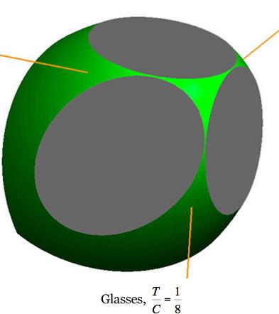
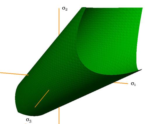
The dynamic graphic shown at the top of this page corresponds to the Ceramics The unusual scaling for the Mises criterion shown above is necessary for the one to one comparison capability with the other cases. When displayed by itself the Mises criterion usually is taken in a long, slender cylindrical form, as shown below
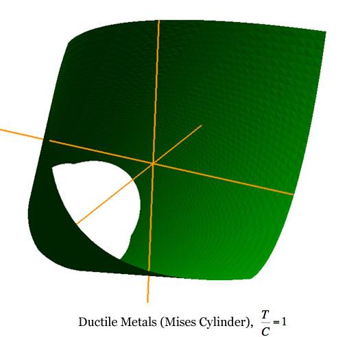
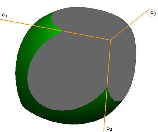
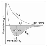
The Mises criterion at T/C=1 represents one of the limiting cases of failure behavior, the ductile limit. Its cylindrical form is the limiting case of the general paraboloid. The other limiting case of failure is that of the brittle limit, at T/C=0. This case is similar to the Geological Materials graphic, being only slightly different when taken to the limit where the apex of the paraboloid coincides with the coordinate origin. Also at this limit, each of the three fracture planes contains the coordinate origin along with two of the axes, thereby requiring that no tensile component of three dimensional stress exist anywhere in the domain. The brittle limit failure surface is shown below
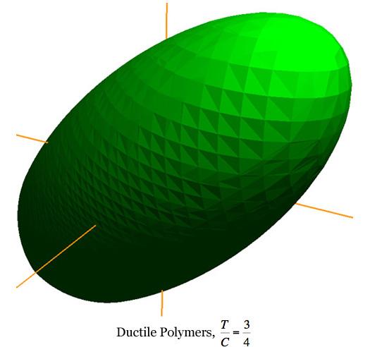
This form has a triangular pyramid shape near the origin, then transitioning into the paraboloid with corners between the two as shown. The two limiting cases of failure are remarkably different, fundamentally different. The most distinctive features of the ductile limit failure criterion are its independence of hydrostatic stress and its symmetry of a type in tensile and compressive stresses. In contrast, the most distinctive features of the brittle limit failure criterion are a strong dependence upon hydrostatic stress and the disallowance of any tensile components of stress, giving it a special type of asymmetry. At a different scale and view angle, the ductile polymers case at T/C=3/4 appears as
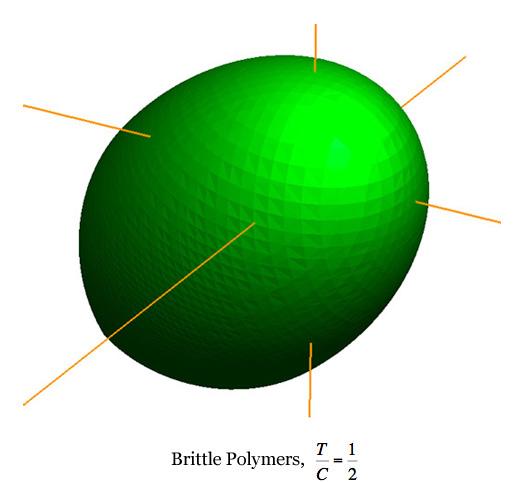
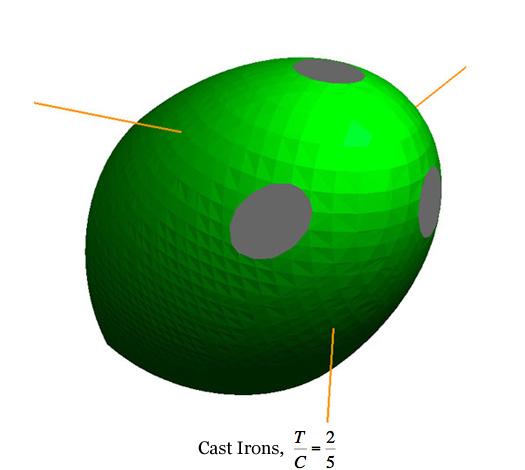
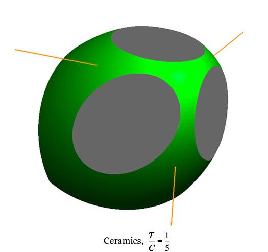
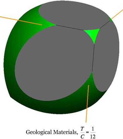
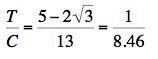
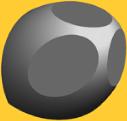
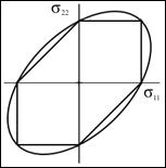
While not having the capability of the ductile limit, this form still reveals the very considerable tensile stress capabilities for this class of materials. Rather than examine other specific cases, some general geometric characteristics will now be noted. In the examples and in general, the complete failure surface is axisymmetric for As T/C diminishes, the apex of the paraboloid moves toward the coordinate origin. For T/C< 1/2 the intersection of the fracture planes with the paraboloidal surface generates elliptical forms. These elliptical intersections become larger as T/C diminishes from the value of 1/2. Going the other direction, the three elliptical intersections reduce to points at T/C=1/2 because the fracture planes become tangent to the paraboloid. For a sufficiently small value of T/C, the adjacent elliptical intersections become tangent with each other. For even smaller values of T/C the elliptical intersections become truncated and contiguous, as shown in the T/C=1/12 graphic. The point of tangency occurs at
These examples show the intricate and non-intuitive failure surface changes that occur in going across the full spectrum of isotropic materials types. They also show how extremely limited the allowable tensile stress regions become relative to the allowable compressive stress regions as T/C decreases. Although the fracture cutoffs are nominally brittle, it does not follow that the remaining paraboloidal part of the failure surface is entirely ductile. For any particular value of T/C there is a mean normal stress controlled plane which is normal to the symmetry axis of the paraboloid and which divides the domain into ductile and brittle parts. This ductile/brittle division plane cuts across the intersection ellipses, where they exist. Despite the exceptionally wide range of failure surface forms for isotropic materials, all are determined by and calibrated by only two failure properties, the uniaxial tensile strength and the uniaxial compressive strength. Failure Characterization outlines the plan of attack in approaching and generating the complex failure scenarios that ultimately result in the forms shown here and many others as well.
Copyright 2009 |
||||||||||||||||||||||||||||||||||||||||||||
Richard M. Christensen |
||||||||||||||||||||||||||||||||||||||||||||
|
||||||||||||||||||||||||||||||||||||||||||||
Recent Additons |
||||||||||||||||||||||||||||||||||||||||||||
Key Junctures |
||||||||||||||||||||||||||||||||||||||||||||
 |
||||||||||||||||||||||||||||||||||||||||||||
General Matters |
||||||||||||||||||||||||||||||||||||||||||||
 |
||||||||||||||||||||||||||||||||||||||||||||
 |
||||||||||||||||||||||||||||||||||||||||||||
 |
||||||||||||||||||||||||||||||||||||||||||||
 |
||||||||||||||||||||||||||||||||||||||||||||
 |
||||||||||||||||||||||||||||||||||||||||||||
Can Atomic/Nano Scale |
||||||||||||||||||||||||||||||||||||||||||||
 |
||||||||||||||||||||||||||||||||||||||||||||
 |
||||||||||||||||||||||||||||||||||||||||||||
 |
||||||||||||||||||||||||||||||||||||||||||||
 |
||||||||||||||||||||||||||||||||||||||||||||
 |
||||||||||||||||||||||||||||||||||||||||||||
 |
||||||||||||||||||||||||||||||||||||||||||||
 |
||||||||||||||||||||||||||||||||||||||||||||
 |
||||||||||||||||||||||||||||||||||||||||||||
 |
||||||||||||||||||||||||||||||||||||||||||||
 |
||||||||||||||||||||||||||||||||||||||||||||
 |
||||||||||||||||||||||||||||||||||||||||||||
Copyright© 2019 |
||||||||||||||||||||||||||||||||||||||||||||