Richard M. Christensen |
||
A Basic Failure Mechanism |
||||||||||||||||
|
||||||||||||||||
 |
||||||||||||||||
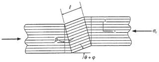
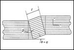
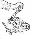
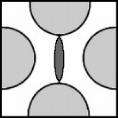
Kink band geometry |
||||||||||||||||
Recent Additons |
||||||||||||||||
 |
||||||||||||
Key Junctures |
||||||||||||
 |
||||||||||||
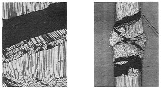
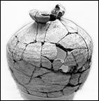
Kink bands in rod, dark regions are expelled material due to polishing, Dr. S. J. DeTeresa |
||||||||||||
General Matters |
|||||||||||||||||||||||||||
 |
|||||||||||||||||||||||||||
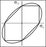
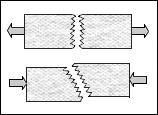
The illustration is a schematic and a micrograph of the failure of an aligned carbon fiber, epoxy matrix lamina (rod) under compressive stress in the fiber direction. The failure mechanism is that of the formation of a kink band, as a basic instability at a critical value of the applied stress. This is the common failure mechanism for carbon-polymer composite systems and it often is the most limiting failure property for these materials. This failure occurrence is not due to the inherent failure properties of the fiber phase nor is it solely due to the properties of the matrix phase. Rather, it involves the cooperative and coordinated motion of both phases to initiate the unstable formation of the kink band. This failure mechanism occurs at the lamina level (scale) and cannot be predicted at the much smaller fiber level nor at the much larger laminate level, thus clearly showing the importance of identifying the proper scale for the failure event. The integration of this failure mechanism into a general anisotropic failure criterion is given in Section III. |
|||||||||||||||||||||||||||
 |
|||||||||||||||||||||||||||
 |
|||||||||||||||||||||||||||
 |
|||||||||||||||||||||||||||
 |
|||||||||||||||||||||||||||
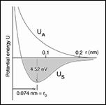
Can Atomic/Nano Scale |
|||||||||||||||||||||||||||
 |
|||||||||||||||||||||||||||
 |
|||||||||||||||||||||||||||
 |
|||||||||||||||||||||||||||
 |
|||||||||||||||||||||||||||
 |
|||||||||||||||||||||||||||
 |
|||||||||||||||||||||||||||
 |
||||||
 |
||||||
 |
||||||||
 |
||||||||
 |
||||||
Copyright© 2019 |
||||||